Raspberry Pi Overview
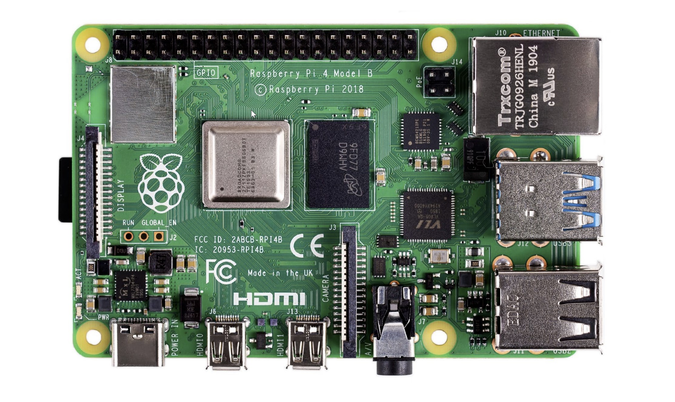
RPI 4 Specifications
| Processor | Broadcom BCM2711, quad-core Cortex-A72 (ARM v8) 64-bit SoC @ 1.5GHz |
| Memory | 1GB, 2GB, 4GB or 8GB LPDDR4 (depending on model) with on-die ECC |
| Connectivity | 2.4 GHz and 5.0 GHz IEEE 802.11b/g/n/ac wireless LAN, Bluetooth 5.0, BLE Gigabit Ethernet, 2 × USB 3.0 ports, 2 × USB 2.0 ports. |
| GPIO | Standard 40-pin GPIO header (fully backwards-compatible with previous boards) |
| Video & sound | 2 × micro HDMI ports (up to 4Kp60 supported), 2-lane MIPI DSI display port, 2-lane MIPI CSI camera port, 4-pole stereo audio and composite video port |
| SD card support | Micro SD card slot for loading operating system and data storage |
| Input power | 5V DC via USB-C connector (minimum 3A), 5V DC via GPIO header (minimum 3A), Power over Ethernet (PoE)–enabled (requires separate PoE HAT) |
| Environment | Operating temperature 0–50ºC |
| Compliance | For a full list of local and regional product approvals, please visit https://www.raspberrypi.org/documentation/hardware/raspberrypi/conformity.md |
| Production lifetime | The Raspberry Pi 4 Model B will remain in production until at least January 2026. |
Raspberry Pi 4 Changes

IO
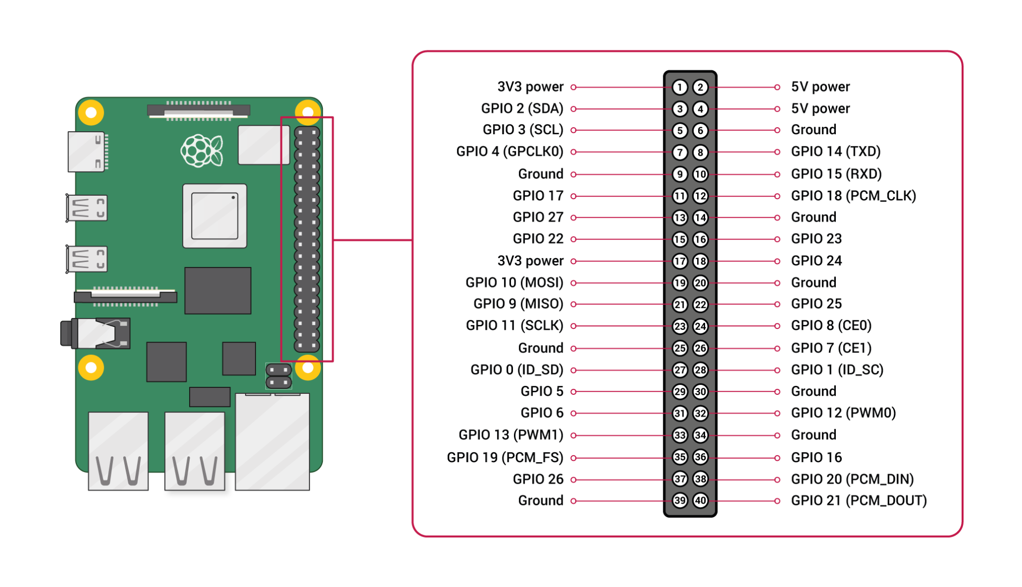
The Raspberry Pi has two rows of GPIO pins along the top edge of the board. GPIO stands for General-Purpose Input/Output.
“These pins are a physical interface between the Raspberry Pi and the outside world. At the simplest level, you can think of them as switches that you can turn on or off (input) or that the Pi can turn on or off (output)” - Raspberry Pi Foundation
| Pin Category | Pin Functionality |
|---|---|
| GPIO | GPIO pins are standard general-purpose pins that can be used for turning external devices, such as an LED, on or off. |
| Power | 5V and 3V3 pins are used to supply 5V and 3.3V power to external components. |
| I2C | I2C pins are used for connecting and hardware communication purposes with I2C compatible external modules. |
| SPI | SPI (Serial Peripheral Interface Bus) pins are also used for hardware communication, but with a different protocol. |
| UART | UART (Universal Asynchronous Receiver / Transmitter) pins are used for serial communication. |
| GND | GND (Ground) pins refer to pins that provide electrical grounding in your circuits. |
GPIO Pinout
The pinout command is a useful tool to reference when working with a Raspberry Pi. pinout is provided by the GPIO Zero Python library and comes installed by default on Raspberry Pi OS distributions. Running the pinout command will return an output similar to that shown below. The output gives a useful visualization of the raspberry pi board and all its connectors, as well as a quick reference pinout of the 40-pin header.
pi@raspberrypi:~ $ pinout
,--------------------------------.
| oooooooooooooooooooo J8   +======
| 1ooooooooooooooooooo  PoE | Net
| Wi                     1o +======
| Fi  Pi Model 4B V1.5   oo      |
|      ,----.     +---+       +====
| |D|  |SoC |     |RAM|       |USB3
| |S|  |    |     |   |       +====
| |I|  `----'     +---+          |
|                   |C|       +====
|                   |S|       |USB2
| pwr   |hd|   |hd| |I||A|    +====
`-| |---|m0|---|m1|----|V|-------'

Revision           : b03115
SoC                : BCM2711
RAM                : 2GB
Storage            : MicroSD
USB ports          : 4 (of which 2 USB3)
Ethernet ports     : 1 (1000Mbps max. speed)
Wi-fi              : True
Bluetooth          : True
Camera ports (CSI) : 1
Display ports (DSI): 1

J8:
   3V3 (1) (2) 5V
 GPIO2 (3) (4) 5V
 GPIO3 (5) (6) GND
 GPIO4 (7) (8) GPIO14
   GND (9) (10) GPIO15
GPIO17 (11) (12) GPIO18
GPIO27 (13) (14) GND
GPIO22 (15) (16) GPIO23
   3V3 (17) (18) GPIO24
GPIO10 (19) (20) GND
 GPIO9 (21) (22) GPIO25
GPIO11 (23) (24) GPIO8
   GND (25) (26) GPIO7
 GPIO0 (27) (28) GPIO1
 GPIO5 (29) (30) GND
 GPIO6 (31) (32) GPIO12
GPIO13 (33) (34) GND
GPIO19 (35) (36) GPIO16
GPIO26 (37) (38) GPIO20
   GND (39) (40) GPIO21

POE:
  TR01 (1) (2) TR00
  TR03 (3) (4) TR02

For further information, please refer to https://pinout.xyz/